...
| Note |
|---|
Thomas Watteyne I need Said Alvarado-Marin and Fil Maksimovic to proof-read this page |
| Table of Contents |
|---|
Target power supply configuration
We want the nRF52840 on the DK to operate at 1.8V. Per the nRF52840 Product Specification version 1.5, we want to be in this situation:v1.5, we want to use this configuration:
DCDCEN0set toDISABLEDREGOUT0set to 1.8VDCDCENset toDISABLED
...
This way, when providing 5V to “Supply” we end up with 1.8V at REGOUT0.
Quirks of the nRF52840-DK
Per the nRF52840-DK User Guide,:
...
That is, to set the VDD_nRF voltage by software:
set the “nRF Power Source“ switch to position “USB“
plug in a (possibly second) micro-USB cable into the “nRF USB“ port
Software configurations
With this in place, we want to set the following registers
DCDCEN0set to0
...
DCDCENset to0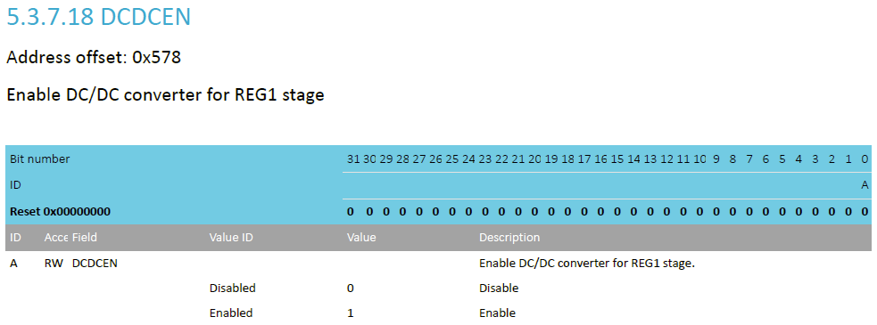
REG0OUTset to0or7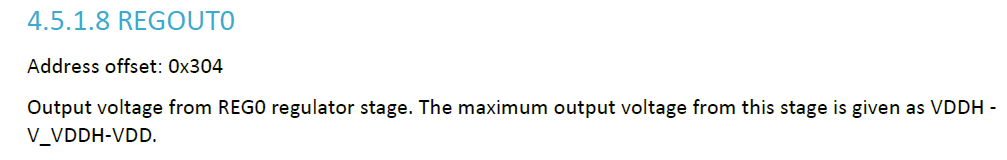
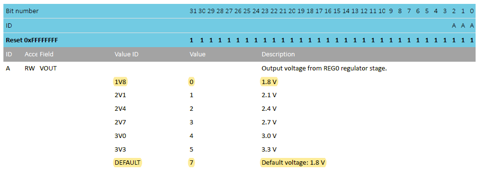
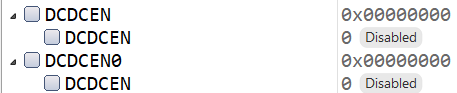
Default configuration
When running project https://github.com/openwsn-berkeley/SCuM-programmer/blob/develop_12/02_firmware_nRF52840-DK/scum-programmer.emProject and observing the register settings on a fresh board, that is by default the configuration:
 | 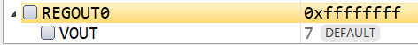 |
|---|
And I confirm that, when plugging in my micro-USB cable into the “nRF USB“ port and setting the “nRF Power Source“ switch to “USB“, I see the LEDs “turning“ (i.e. the program is running) but very dim
| Info |
|---|
I only have a single USB cable, so I don’t have the main USB power plugged in; I’m pretty sure that wouldn’t change the power source of the nRF. |
Notes about UICR
Of course, register REGOUT0 is non-volatile, i.e. it is part of the UICR registers which are mapped to a flash page, so its contents stays even after power cycling the board. If a different program was run which write a different value to REGOUT0 , the board would be running at a different voltage.
The recommended behavior of the scum-programmer is:
when started, check the value of
REGOUT0if different that the default value
7, write7and soft-resetthe board will then reboot at 1.8V
The user doesn’t have to worry about this, but should only plug in SCuM once she confirms the LEDs are dim
About Said’s technique
Said Alvarado-Marin 's technique is to provide add the following to flash_placement.xml
| Code Block |
|---|
<MemorySegment name="UICR" start="$(UICR_START)" size="$(UICR_SIZE)">
    <ProgramSection alignment="4" keep="Yes" load="Yes" name=".uicr_regout0" start="0x10001304" size="4"/>
</MemorySegment> |
this “declares” the UICR memory segment so it can be referred to by a header file.
For this to work, the projet file (the main .emProj file) must declare the following variables
UICR_START = 0x10001000UICR_SIZE = 0x308
Then add a uicr_config.h file which contains teh following single line:
| Code Block |
|---|
const uint32_t REGOUT0 __attribute__((section(".uicr_regout0"))) = 1; // 0 = 1.8v, 1 = 2.1v, 2 = 2.4v, 3 = 2.7v, 4 = 3.0v, 5 = 3.3v |
In essence, this while technique just writes the REGOUT0 register. Using this super convoluted approach allows the program to change the voltage without touching the C code, which is useful if you have compile C code which isn’t yours and you want to change the voltage. But this technique is by no means AFAICT needed. I’d like to get input from Said Alvarado-Marin on this.
Also, I don’t understand why we use the setting to 1 (2.1V) and not 0 or 7 (1.8V). Again, would like input from Said Alvarado-Marin .
Resources
nRF52840 Product Specification v1.5 https://infocenter.nordicsemi.com/pdf/nRF52840_PS_v1.5.pdf
nRF52840-DK User Guide v1.0.0 https://infocenter.nordicsemi.com/pdf/nRF52840_DK_User_Guide_20201203.pdf