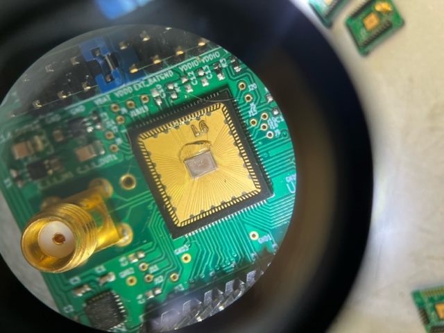
L6/L7:
Sulu V1 boards
Immediately after getting boards from Digicom:
L6 had noticeable epoxy deformation on Quik-Pak SCuM. L7 no noticeable deformation.
Pin headers hand-soldered by us. Josh tested both connections to SCuM and could program both initially.
A mistake on the BOM led to inductors not being soldered on by Digicom so DC-DC converters did not work. Alex was able to reheat the solder on the inductor pads for both boards to add the inductors. Afterwards:
After adding the inductors, L6 DC-DC converters functional but SCuM disconnected. We thought that heating the board to the point that the inductor pad solder melted might have loosened the SCuM Quik-Pak and a very small movement might have disconnected it.
When tested with 1.8 V 2/11/22:
300 uA on VBAT
2.2 mA on VDDD
0.4 uA on VDDIO
After adding the inductors, L7 functionality did not change. It could still easily be programmed, but DC-DC converters were still disconnected. Due to L6 issues, we decided not to retry soldering on inductors.
When tested with 1.8 V 2/11/22:
18 mA on VBAT
48.5 mA on VDDD
2.3 uA on VDDIO
.jpeg?version=1&modificationDate=1644473824355&cacheVersion=1&api=v2&width=217&height=162)
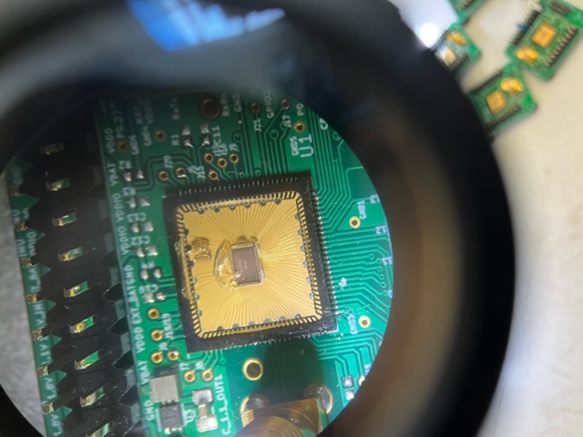
L8/L9/L10:
Sulu V1 boards
Pin headers soldered on by Austin.
All 3 boards did not draw current when connected to VBAT.
Due to last minute changes with which inductors were used, Digicom initially placed the old inductors and later swapped them out for the correct ones. Digicom said they looked at the board under and xray machine and the connections looked ok.
Deformations in L8
When tested with 1.8 V 2/11/22:
0 uA on VBAT
0 uA on VDDD
0 uA on VDDIO
L10
When tested with 1.8 V 2/11/22:
0 uA on VBAT
0 uA on VDDD
0 uA on VDDIO
.jpeg?version=1&modificationDate=1643797340846&cacheVersion=1&api=v2&width=210&height=157)
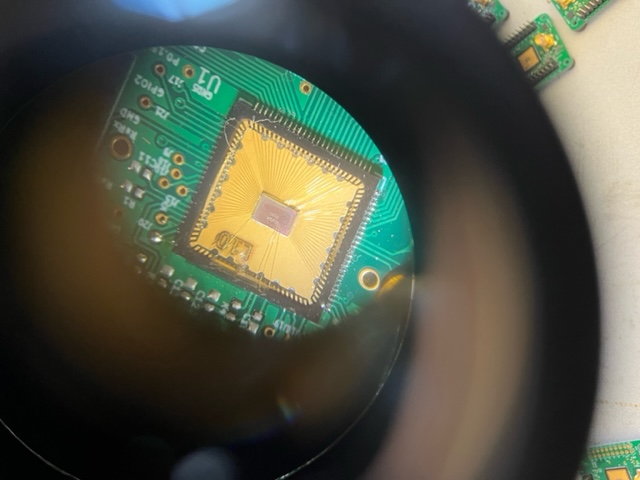
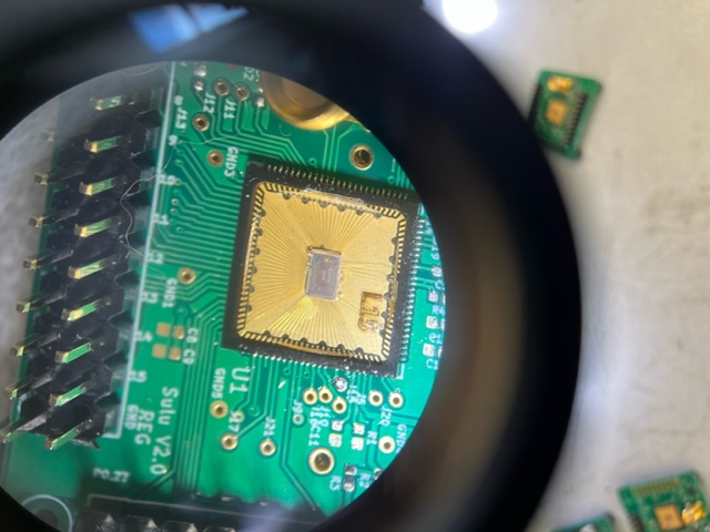
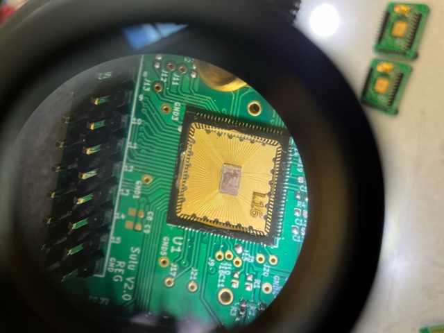
L14/L15/L16:
Sulu V2 boards
L15 had noticeable epoxy deformation on Quik-Pak SCuM.
When tested with 1.8 V 2/11/22:
425 uA on VBAT
0 uA on VDDD
0 uA on VDDIO
Pin headers soldered on by Digicom
L14 and L16 did not draw current when connected to VBAT. L15 did draw expected current when connected to VBAT, but did not draw current when connected to VDDD.
All 3 SCuM were confirmed 5 days earlier to successfully program with 3WB using the probe station.
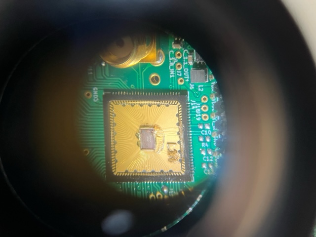
L17/L19:
Sulu V2 boards
L19 had noticeable epoxy deformation on Quik-Pak SCuM.
L17 had a noticeable crack in the epoxy.
Pin headers soldered on by Digicom
No current drawn from either board from any location.
Both SCuM were confirmed 1 day earlier to successfully program with 3WB using the probe station.
.jpeg?version=1&modificationDate=1644473787468&cacheVersion=1&api=v2&width=217&height=289)
.jpeg?version=1&modificationDate=1644473787475&cacheVersion=1&api=v2&width=217&height=162)
L24/L25:
Digicom Assembly Steps:
Clean board and bake it to get rid of moisture
Print solder paste onto board
Use a machine to place smd components
SCuM placed by hand
Use oven to reflow.
Use no clean solder so there is no need to clean it again
Check if the board needs to be touched up
Both boards could be programmed to communicate with Open Mote when received from Digicom
No through hole components/pin headers were added initially
L25 has pin headers added.
Confirmed to work with 3WB and UART